A prover is a mobile automated device that provides on-site calibration to ensure that flow meters used in fiscal and custody transfer applications continue to function properly and to assure compliance with Directive 17, BCOGC, ABSA.
Due to the fact that field conditions may significantly alter from those at the time the meter was calibrated, meter proving ensures optimal performance throughout the device's lifetime.
Maintaining a regular schedule for meter proving maintenance helps keep your operation running efficiently and informs operators to possible problems before they cause significant financial or technical damage. By providing a stationary or mobile meter proving solution that will assist calibration of flow meters before, during or after a transfer, provers ensure that a custody transfer system is giving the most accurate measurement possible
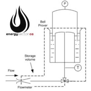
Bell Proving Diagram
Manual Bell Prover: Since the early 1900s, bell provers have been the most common reference standard used in gas meter proving. Bell scales are unique to each bell and are attached vertically with a needle-like pointer. Temperature inconsistencies between the bell air, meter and connecting hoses can account for most meter proof inaccuracies.
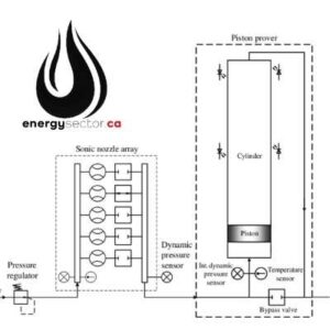
Sonic nozzle prover diagram
Automated Bell Prover: With the introduction of programmable logic controllers (PLC), gas meter proving facilities were able to automate the majority of the manual bell prover's processes and calculations. The PLC was phased out in the early 1990s in favour of PACs (Programmable Automated
Controls) and newer computer systems. Sensors that read a meter's index were added to further automate the process, eliminating most of the human error inherent with manual bell provers.
Sonic Nozzle Prover: Flow rates are precisely measured using vacuum-driven provers equipped with arrays of sonic nozzles. Most sonic nozzle provers can provide metre proofs to the user or a computer for automation. They can also send critical data to database systems through a network. Computers and PAC systems automate the procedure.
The fluid is collected in a test vessel and compared to the gross supplied quantity of the meter under test in the static condition. This is generally an open system (but will be closed when testing with a volatile substance). The fluid stays in a closed system in the dynamic scenario, where the pulse registration of the meter under test and the standard prover are directly compared. During the metre factor verification, there is no disruption to the routine flow operation.
It is important to remember that flow metering systems serve as the "cash registers" for all petroleum activities, which means that inaccuracies in meter factor may and will result in massive financial losses in an extremely short period of time. The goal of meter verification, also known as meter proving, is to give precise measurement in order to reduce losses and enhance revenues.
You have 3 categories of measuring devices used in verification in the petroleum business today: test measure tank provers, volumetric displacement provers, and master meters. Test measure tank provers are definitely the most popular type of measurement hardware employed in the oil and gas vertical. The type of equipment to be utilized is identified by the accuracy and reliability demands, testing flow rates, and external conditions. The accuracy uncertainty is shown by tank volume mass; tanks 100 gallons or less differ from 0.015 percent for 100 gallon cans to 0.3 percent for 1 gallon cans. Tanks larger than 100 gallons range from 0.015 percent to 0.3 percent. There are actually a few applications for the master meters prover solution in terms of proving. The required verification of the master meter's accuracy must be confirmed using either a displacement type or a volumetric tank prover, according to the situation.
A method for calculating pulse interpolation data to capture total measured signals with less than ten thousand (10,000) observed pulses was developed in the early 1980s. This standardized use of Double Chronometry Pulse Interpolation inside the flow computer allowed the approval of UDCDP for the Liquid Oil/Gas Industry in the first place. Because of advancements in meter technology and bigger displacement volumes, its now possible to accomplish higher levels of repeatability and uncertainty validation which are considerably lower than the industry-accepted norms of accuracy and precision.
The system of double chronometry is a basic procedure. To be able to achieve high frequency timing, each volume displacement and each time period for the total number of full meter pulses gathered during that time period are measured and timed independently using high frequency time bases. Modern computer time bases, including those now employed in flow computers, function at a frequency of at least 1MHz, producing an uncertainty that is notably greater than the needed 1 part in 10,000.
The pulse interpolation process allows for the gathering of a large number of measurements at the same time. Clock one is initiated by the detector switch signal from the upstream detector switch, and clock two is initiated by the detector switch signal from the downstream detector switch. The first complete pulse is detected by the detector switch signal from clock two (ET2 for the elapsed time to measure whole pulses). When the downstream detector switch is switched off, the accumulation of clock three is brought to a close as well. Because of the use of many measurements within the required repeatability values, it is feasible to determine the new K-Factor.
The adoption of multi-pass runs for proving by the industry allows for adjustments in repeatability restrictions while still achieving the 0.0027 percent uncertainty requirement. This is especially true when employing newer technologies such as Coriolis and Ultrasonic, as well as the pulse signals produced by these technologies. This allows for more efficient and speedier verification of large bore meters to an acceptable repeatability value, as opposed to employing a bidirectional pipe/ball prover in the previous method of verification.
Meter proving services are most commonly used in areas throughout Alberta like Grande Prairie, Fort McMurray, Red Deer, Lloydminster, Red Earth, Drayton Valley and Whitecourt. And in British Columbia meter provers can be found in Dawson Creek, and Fort St. John. There are also a number of meter proving companies located in Ontario, Canada also.
Full On-Site Custody Transfer Meter Proving
- Custody Transfer Meter Proving, Master Meter Proving, and Meter Inspection
- Fast proving times per meter utilizing Small Volume Provers
- “Cloud-based” remote customer access to past proving reports
- Fleet of inline and bench provers that are all 100 percent mobile
- All meter provers are Directive 17, BCOGC, ABSA compliant
It is necessary to employ a higher accuracy meter (that has been validated to a higher accuracy level than the meter under test) in conjunction with the meter under test in order to perform master meter proving.
In contrast to field calibration, which involves calibrating the meter using the real process as the input method, bench meter calibration involves proving at a calibration bench by replicating the process.
Is the process of comparing the preset scale or metering of a flow meter to a standard scale of measurement and then modifying the metering to comply to the standard scale of measurement (also known as calibration).
A volumetric flow meter prover measures the volume of a material moving through a certain point in a given amount of time, either directly or indirectly. Volumetric flow rate is measured in a variety of units.
A sphere prover, also known as a ball prover or pipe prover, is based on the repetitive displacement of a known volume of liquid from a calibrated piece of pipe between two detectors.
A calibration tank for large-volume liquid flow metres. Prover tanks are often installed on transportable trailer units that may be towed from one job site to another by vehicle.